

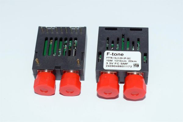
Product Description
F-tone’s FTTR-xxL2-xxxx series of transceiver modules are the perfect solution for ultra-low speed communication networks.These transceiver modules support data rates up to 10Mbps. The module is fully compliant with the Multi-sourced 1×9 protocol.These transceiver modules provides the system designer with products to RS232/RS485/RS422 receptacle fiber transmission.
Product Features
● VCSEL/FP Laser Diode Transmitter
● Up to 2 Km on 62.5/125μm MMF,Up to 40 Km on 9/125μm SMF
● 3.3V or 5.0V power supply
● SC/ST/FC duplex optical interface
● (LV)TTL Inputs / Outputs and or( LV)TTL signal detect
● Class 1 Laser International Safety Standard IEC 825 Compliant
● Operating case temperature range (Standard:0 to +70℃) or (Industrial: -40°C to +85°C)
Application
● RS232/RS485/RS422 receptacle fiber transmission
● Other optic link
Absolute Maximum Ratings
Operating of the transceiver beyond the Absolute Conditions Listed in Table 1 will degrade or damage the product. It’s not implied that the product would function above the recommended operating environment, it’s possible to reduce the reliability and lifetime of device if Recommended Operating Environment is exceeded (Refer to table 2)
Table 1–– Absolute Maximum Conditions
| Parameter | Symbol | Min | Max | Units | Note | |
| Storage Temperature | TST | -40 | +85 | ℃ | – | |
| Relative Humidity | RH | 5 | 95 | % | – | |
| Supply Voltage | 3.3V power | VCC | 0 | +3.6 | V | – |
| 5V power | 0 | +6 | – | |||
Table 2–– Recommended Operating Environment and Electrical Characteristics
| Parameter | Symbol | Min | Typ | Max | Units | Note | |
| Supply Voltage | 3.3V power | VCC | +3.1 | +3.3 | +3.5 | V | – |
| 5V power | +4.75 | +5.0 | +5.25 | – | |||
| Supply Current | Icc | – | – | 160 | mA | – | |
| Operating Case Temperature | TOP | 0 | – | +70 | ℃ | 1 | |
| -40 | – | +85 | 2 | ||||
| Data Rate | B | DC | – | 10 | Mbps | – | |
| Soldering temperature | – | – | – | 350 | ℃ | 3 | |
| Soldering duration | – | – | – | 10 | Sec | 3 | |
Note
1.standard level
2.industrial level
3.Not recommended wave soldering.
Optical Parameters
Table 3–– FTTR-85L2-02 Transceiver Optical Characteristics(Ambient Operating Temperature Ta=+25±5°C, VCC = 3.3 or 5.0±0.2V)
| Parameter | Symbol | Min | Typ | Max | Units | Note | |
| Transmitter | |||||||
| Data rate | B | DC | – | 10 | Mbps | – | |
| Output Center Wavelength | λc | 830 | 850 | 860 | nm | – | |
| Output Spectral width (RMS) | λ | – | – | 0.85 | nm | – | |
| Average Optical Output Power | Po | -10 | – | -3 | dBm | 1,2 | |
| Extinction Ratio | ER | 10 | – | – | dB | 1,2 | |
| Receiver | |||||||
| Receiver Sensitivity | Pmin | – | – | -14 | dBm | 1,2 | |
| Receiver Saturation | Pmax | -3 | – | – | dBm | 1,2 | |
| Operation Center Wavelength | λc | 770 | – | 860 | nm | – | |
| SD | Deassert | PD | -30 | – | – | dBm | 1,2 |
| Assert | PA | – | – | -14 | dBm | 1,2 | |
| SD Hysteresis | SDHYS | 0.5 | – | – | dB | – | |
Note1:The optical power is launched into 62.5/125μm MMF.
Note2:With 10Mbps. If keep 0 1 level duty ratio of 45%:55%, sensitivity control as ≤- 12dBm.
Table 4—– FTTR-M13L2-02 Transceiver Optical Characteristics
(Ambient Operating Temperature Ta=+25±5°C, VCC = 3.3 or 5.0±0.2V)
| Parameter | Symbol | Min | Typ | Max | Units | Note | |
| Transmitter | |||||||
| Data rate | B | DC | – | 10 | Mbps | – | |
| Output Center Wavelength | λc | 1260 | 1310 | 1360 | nm | – | |
| Output Spectral width (RMS) | λ | – | – | 4 | nm | – | |
| Average Optical Output Power | Po | -10 | – | -3 | dBm | 1,2 | |
| Extinction Ratio | ER | 10 | – | – | dB | 1,2 | |
| Receiver | |||||||
| Receiver Sensitivity | Pmin | – | – | -15 | dBm | 1,2 | |
| Receiver Saturation | Pmax | -3 | – | – | dBm | 1,2 | |
| Operation Center Wavelength | λc | 1260 | – | 1620 | nm | – | |
| SD | Deassert | PD | -30 | – | – | dBm | 1,2 |
| Assert | PA | – | – | -15 | dBm | 1,2 | |
| SD Hysteresis | SDHYS | 0.5 | – | – | dB | – | |
Note1:The optical power is launched into 62.5/125μm MMF.
Note2:With 10Mbps. If keep 0 1 level duty ratio of 45%:55%, sensitivity control as ≤- 14dBm.
Table 5—– FTTR-13L2-20 Transceiver Optical Characteristics
(Ambient Operating Temperature Ta=+25±5°C, VCC = 3.3 or 5.0±0.2V)
| Parameter | Symbol | Min | Typ | Max | Units | Note | |
| Transmitter | |||||||
| Data rate | B | DC | – | 10 | Mbps | – | |
| Output Center Wavelength | λc | 1260 | 1310 | 1360 | nm | – | |
| Output Spectral width (RMS) | λ | – | – | 4 | nm | – | |
| Average Optical Output Power | Po | -10 | – | -3 | dBm | 1,2 | |
| Extinction Ratio | ER | 10 | – | – | dB | 1,2 | |
| Receiver | |||||||
| Receiver Sensitivity | Pmin | – | – | -15 | dBm | 1,2 | |
| Receiver Saturation | Pmax | -3 | – | – | dBm | 1,2 | |
| Operation Center Wavelength | λc | 1260 | – | 1620 | nm | – | |
| SD | Deassert | PD | -30 | – | – | dBm | 1,2 |
| Assert | PA | – | – | -15 | dBm | 1,2 | |
| SD Hysteresis | SDHYS | 0.5 | – | – | dB | – | |
Note1:The optical power is launched into 9/125μm SMF.
Note2:With 10Mbps. If keep 0 1 level duty ratio of 45%:55%, sensitivity control as ≤- 14dBm.
Table 6—– FTTR-13L2-40 Transceiver Optical Characteristics
(Ambient Operating Temperature Ta=+25±5°C, VCC = 3.3 or 5.0±0.2V)
| Parameter | Symbol | Min | Typ | Max | Units | Note | |
| Transmitter | |||||||
| Data rate | B | DC | – | 10 | Mbps | – | |
| Output Center Wavelength | λc | 1260 | 1310 | 1360 | nm | – | |
| Output Spectral width (RMS) | λ | – | – | 4 | nm | – | |
| Average Optical Output Power | Po | -5 | – | 0 | dBm | 1,2 | |
| Extinction Ratio | ER | 10 | – | – | dB | 1,2 | |
| Receiver | |||||||
| Receiver Sensitivity | Pmin | – | – | -16 | dBm | 1,2 | |
| Receiver Saturation | Pmax | -3 | – | – | dBm | 1,2 | |
| Operation Center Wavelength | λc | 1260 | – | 1620 | nm | – | |
| SD | Deassert | PD | -30 | – | – | dBm | 1,2 |
| Assert | PA | – | – | -16 | dBm | 1,2 | |
| SD Hysteresis | SDHYS | 0.5 | – | – | dB | – | |
Note1:The optical power is launched into 9/125μm SMF.
Note2:With 10Mbps. If keep 0 1 level duty ratio of 45%:55%, sensitivity control as ≤- 15dBm.
Electrical Parameters
Table 7—– Transceiver Electrical Characteristics
(Ambient Operating Temperature Ta=+25±5°C, VCC = 3.3 or 5.0±0.2V)
| Parameter | Symbol | Min | Typ | Max | Units | Note | |
| Supply Voltage | 3.3V power | VCC | +3.1 | +3.3 | +3.5 | V | – |
| 5V power | +4.75 | +5.0 | +5.25 | – | |||
| Supply Current | ICC | – | – | 160 | mA | – | |
| Transmitter | |||||||
| Data Input Voltage – Low | VIL | 0 | – | 0.8 | V | 1 | |
| Data Input Voltage – High | VIH | 2 | – | VCC | V | 1 | |
| Receiver | |||||||
| Data Output Voltage – Low | VOL | 0 | – | 0.4 | V | 1 | |
| Data Output Voltage – High | VOH | 2.4 | – | VCC | V | 1 | |
| SD Output Voltage-Low | VOL | 0 | – | 0.8 | V | 1 | |
| SD Output Voltage-High | VOH | 2 | – | VCC | V | 1 | |
Note1:(LV)TTL signal detect
This product belongs to F-tone Networks' optical components product line. For detailed specifications, please contact our sales team. Thank you!
Important Notice:
Performance figures, data and any illustrative material provided in this data sheet are typical and must be specifically confirmed in writing by F-tone Networks before they become applicable to any particular order or contract. In accordance with the F-tone Networks policy of continuous improvement specifications may change without notice.
The publication of information in this data sheet does not imply freedom from patent or other protective rights of F-tone Networks or others. Further details are available from any F-tone Networks sales representative.
HFBR-1414TZ | HFBR-2412TZ AVAGO compatible full series
-
-
Compatible AVAGO AFBR-2418TZ La fibre optique 850 nm Le dispositif de réception optoélectronique haute performance DC-50 MBd
Prix habituel $0.00Prix habituel -
Fibre optique 850 nm compatible AVAGO HFBR-1412TZ Dispositif émetteur-récepteur optoélectronique hautes performances DC-5 MBd
Prix habituel $0.00Prix habituel -
Fibre optique 850 nm compatible AVAGO HFBR-2412TZ Dispositif émetteur-récepteur optoélectronique hautes performances DC-5 MBd
Prix habituel $0.00Prix habituel

HFBR-1521Z | HFBR-2521Z | AFBR-1629Z | HFBR-2629Z AVAGO compatible full series
-
Module émetteur-récepteur SFP+ BiDi 10GBASE-BX20-D 1330 nm-TX/1270 nm-RX 20 km DDM Simplex LC SMF compatible Cisco
Prix habituel $0.00Prix habituel -
Fibre optique 650 nm compatible AVAGO HFBR-1521Z Dispositif émetteur-récepteur optoélectronique hautes performances DC-5 MBd
Prix habituel $0.00Prix habituel -
Fibre optique 650 nm compatible AVAGO HFBR-1521Z Dispositif émetteur-récepteur optoélectronique hautes performances DC-5 MBd
Prix habituel $0.00Prix habituel -
Fibre optique 650 nm compatible AVAGO HFBR-1521Z Dispositif émetteur-récepteur optoélectronique hautes performances DC-5 MBd
Prix habituel $0.00Prix habituel


Power and Wavelength Testing
Test the signal delivering strength and wavelength, to ensure the signal decoding capacity of the receiver, and the wavelength remains consistent from the transmitter to the receiver.

Traffic Testing
Test the bit error rate and packet loss rate, to make them meet the corresponding standards and ensure the performance of transceivers.

Optical Performance Testing
Test the transceivers' eye diagram situation, receiving sensitivity, extinction ratio, wavelength, light-emitting, light-receiving, current and voltage, to ensure the signal quality, stability and reliability of the transmission.

End Face Testing
Check the end face of the transceivers and keep them clean for more stable data transmission, better performance, and durability.

Various Switch Tests
Every module is quality tested for compatibility in the multi-brand switches environment, guaranteeing flawless operations.