


Part Number: FTOFMM-MBI-X
MaxBand® OM2+/OM3/OM4 Bending Insensitive Multimode Fiber 50.4km Length in Spool
MaxBand® OM2+ Bending Insensitive Multimode fiber complies with or exceeds ISO/IEC 11801-1 OM2 specification, IEC 60793-2-10 A1-OM2 specification, and TIA-492AAAF A1-OM2 specification.
MaxBand® OM3/OM4 Bending Insensitive Multimode fibers comply with or exceed ISO/IEC 11801-1 OM3/OM4 specifications, IEC 60793-2-10 A1-OM3/A1-OM4 specfications, and TIA-492AAAF A1-OM3/A1-OM4 specifications.
| Features | Benefits and Applications |
|---|---|
| ● Optimized for 850nm VCSEL ● Compatibility with current OM2+/OM3/OM4 multimode fiber ● Superior geometry uniformity ● Low attenuation ● High bandwidth ● Low differential mode delay (DMD) |
● Data centers ● Data storage networks ● High-performance computing centers a ● Office centers ● Local area networks (LAN) ● 1 & 10 & 40 & 100 & 400 Gb/s Ethernet |
| ● Very low macro-bending sensitivity | ● Supports the use and installation of optical cables with a small bending radius |
| ● Coated with proprietary dual layer UV curable acrylate | ● High resistance to micro-bending ● Optimized performance in tight-buffer cable applications ● Stable performance over a wide range of environmental conditions |
Specification
| Characteristics | Conditions | Specified values | Units |
|---|---|---|---|
| Geometry Characteristics | |||
| Core Diameter | -- | 50±2.5 | [μm] |
| Core Non-Circularity | -- | ≤5.0 | [%] |
| Cladding Diameter | -- | 125.0±1.0 | [μm] |
| Cladding Non-Circularity | -- | ≤0.6 | [%] |
| Coating Diameter | -- | 245±7 | [μm] |
| Coating/Cladding Concentricity Error | -- | ≤10.0 | [μm] |
| Coating Non-Circularity | -- | ≤6.0 | [%] |
| Core/Cladding Concentricity Error | -- | ≤1.0 | [μm] |
| Delivery Length | -- | up to 8.8 | [km/reel] |
| Optical Characteristics | |||
| Attenuation | 850nm | ≤2.4 | [dB/km] |
| 1300nm | ≤0.6 | [dB/km] | |
| -- | -- | MaxBand® OM2+/OM3/OM4 Bend Insensitive | |
| Overfilled Modal Bandwidth | 850nm | ≥700/≥1500/≥3500 | [MHz·km] |
| 1300nm | ≥500/≥500/≥500 | [MHz·km] | |
| Effective Modal Bandwidth | 850nm | ≥950/≥2000/≥4700 | [MHz·km] |
| Application support distance on | -- | -- | -- |
| 40GBASE-SR4 / 100GBASE-SR101 | 850nm | -/140/170 | [m] |
| 10GBASE-SR | 850nm | 150/300/550 | [m] |
| 1000BASE-SR | 850nm | 750/1000/1100 | [m] |
| DMD Specification | Compliant with and more stringent than the requirements of IEC60793-2-10 | -- | |
| Numerical Aperture | -- | 0.200±0.015 | -- |
| Group Refractive Index | 850nm | 1.482 | -- |
| 1300nm | 1.477 | -- | |
| Zero Dispersion Wavelength(λ0) | -- | 1295-1340 | [nm] |
| Zero Dispersion Slope(S0) | 1295nm≤λ0≤1310nm | ≤0.105 | [ps/(nm2·km)] |
| 1310nm≤λ0≤1340nm | ≤0.000375(1590-λ0) | [ps/(nm2·km)] | |
| Macrobending Loss2 | -- | -- | -- |
| 2 Turns @ 15 mm Radius | 850nm | ≤0.1 | [dB] |
| 1300nm | ≤0.3 | [dB] | |
| 2 Turns @ 7.5 mm Radius | 850nm | ≤0.2 | [dB] |
| 1300nm | ≤0.5 | [dB] | |
| Backscatter Characteristics | 1300nm | ||
| Step(Mean of Bidirectional Measurement) | -- | ≤0.10 | [dB] |
| Irregularities Over fiber Length and Point Discontinuity | -- | ≤0.10 | [dB] |
| Attenuation Uniformity | -- | ≤0.08 | [dB/km] |
| Environmental Characteristics | 850nm & 1300nm | ||
| Temperature Cycling | -60℃ to 85℃ | ≤0.10 | [dB/km] |
| Temperature-Humidity Cycling | -10℃ to 85℃,4% to 98% RH | ≤0.10 | [dB/km] |
| Water Immersion | 23℃, 30 days | ≤0.10 | [dB/km] |
| Dry Heat | 85℃,30 days | ≤0.10 | [dB/km] |
| Damp Heat | 85℃, 85% RH,30 days | ≤0.10 | [dB/km] |
| Mechanical Specification | |||
| Proof Test | -- | ≥9.0 | [N] |
| -- | ≥1.0 | [%] | |
| -- | ≥100 | [kpsi] | |
| Coating Strip Force | typical average force | 1.5 | [N] |
| peak force | ≥1.3, ≤8.9 | [N] | |
| Dynamic Stress Corrosion Susceptibility Parameter(nd, typical) | -- | 20 | -- |
Remarks: 1. Support distances considering maximum cable attenuation of 3.0 dB/km at 850 nm,
maximum total splice/connector loss of 1.0 dB and VCSELs maximum RMS spectral width ≤ 0.45 nm.
2. The launch condition for the macrobending loss measurement fulfils that described in IEC 61280-4-1.
This product belongs to F-tone Networks' optical components product line. For detailed specifications, please contact our sales team. Thank you!
Important Notice:
Performance figures, data and any illustrative material provided in this data sheet are typical and must be specifically confirmed in writing by F-tone Networks before they become applicable to any particular order or contract. In accordance with the F-tone Networks policy of continuous improvement specifications may change without notice.
The publication of information in this data sheet does not imply freedom from patent or other protective rights of F-tone Networks or others. Further details are available from any F-tone Networks sales representative.
HFBR-1414TZ | HFBR-2412TZ AVAGO compatible full series
-
-
Compatible AVAGO AFBR-2418TZ La fibre optique 850 nm Le dispositif de réception optoélectronique haute performance DC-50 MBd
Prix habituel $0.00Prix habituel -
Fibre optique 850 nm compatible AVAGO HFBR-1412TZ Dispositif émetteur-récepteur optoélectronique hautes performances DC-5 MBd
Prix habituel $0.00Prix habituel -
Fibre optique 850 nm compatible AVAGO HFBR-2412TZ Dispositif émetteur-récepteur optoélectronique hautes performances DC-5 MBd
Prix habituel $0.00Prix habituel

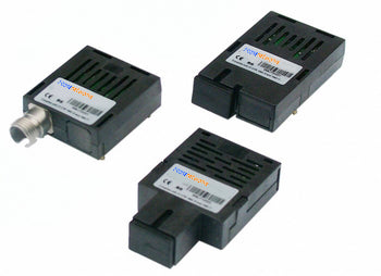
HFBR-1521Z | HFBR-2521Z | AFBR-1629Z | HFBR-2629Z AVAGO compatible full series
-
Module émetteur-récepteur SFP+ BiDi 10GBASE-BX20-D 1330 nm-TX/1270 nm-RX 20 km DDM Simplex LC SMF compatible Cisco
Prix habituel $0.00Prix habituel -
Fibre optique 650 nm compatible AVAGO HFBR-1521Z Dispositif émetteur-récepteur optoélectronique hautes performances DC-5 MBd
Prix habituel $0.00Prix habituel -
Fibre optique 650 nm compatible AVAGO HFBR-1521Z Dispositif émetteur-récepteur optoélectronique hautes performances DC-5 MBd
Prix habituel $0.00Prix habituel -
Fibre optique 650 nm compatible AVAGO HFBR-1521Z Dispositif émetteur-récepteur optoélectronique hautes performances DC-5 MBd
Prix habituel $0.00Prix habituel


Power and Wavelength Testing
Test the signal delivering strength and wavelength, to ensure the signal decoding capacity of the receiver, and the wavelength remains consistent from the transmitter to the receiver.

Traffic Testing
Test the bit error rate and packet loss rate, to make them meet the corresponding standards and ensure the performance of transceivers.

Optical Performance Testing
Test the transceivers' eye diagram situation, receiving sensitivity, extinction ratio, wavelength, light-emitting, light-receiving, current and voltage, to ensure the signal quality, stability and reliability of the transmission.

End Face Testing
Check the end face of the transceivers and keep them clean for more stable data transmission, better performance, and durability.

Various Switch Tests
Every module is quality tested for compatibility in the multi-brand switches environment, guaranteeing flawless operations.