


Part Number: FTOFSM-G654E-X
G.654.E FarBand® Ultra Low Loss and Large Effective Area Single-mode Fiber 50.4km Length in Spool
For the next generation optical transmission network, lower attenuation or larger effective area of the fiber can help the system meet 3U (Ultra high speed, Ultra large capacity, Ultra long-haul) features. Now YOFC can deliver you larger effective area and lower attenuation within one fiber: FarBand® Ultra.
Product standards
FarBand® Ultra fiber complies with or exceeds the ITU-T G.654.B/E recommendation and IEC 60793-2-50 B1.2 specification.
Product advantage
● Larger effective area reduces nonlinear effect and enables higher signal power launched into the transmission system.
● Enable higher transmission speeds with more wavelengths over ultra long-haul distances.
● Lower attenuation level which meets the demand of extended long distance transmission
● Reduce number of repeaters and minimize CAPEX and OPEX.
● Lower bending induced loss to meet complicated deployment conditions and cable structures.
How to calculate the contribution of larger effective area and lower attenuation?
Based on the formula of OSNR, lower attenuation and larger effective area will increase OSNR of optical transmission system. And FOM (Figure of Merit) is established to calculate the contribution of effective area and attenuation. As shown in the table, YOFC ultra low loss and large effective area fiber can provide greater performance improvement than ultra low loss fiber below, or low loss and large effective fiber.
| Fiber Type | Att. | Aeff. | FOM |
|---|---|---|---|
| SSMF(Ref.) | 0.2 | 80 | / |
| LL | 0.18 | 80 | 1.6 |
| ULL | 0.17 | 80 | 2.3 |
| ULL | 0.15 | 80 | 3.8 |
| LL-LAF | 0.18 | 130 | 4.9 |
| ULL-LAF | 0.16 | 110 | 5.8 |
| ULL-LAF | 0.16 | 130 | 6.4 |
Specification
| Characteristics | Conditions | Specified values | Units | |||
|---|---|---|---|---|---|---|
| Optical Specifications | ||||||
| Nominal Effective Area | 1550nm | 110 | 125 | [μm2] | ||
| Mode Field Diameter | 1550nm | 11.4-12.2 | 12.0-13.0 | [μm] | ||
| Attenuation | 1550nm | ≤0.17 | [dB/km] | |||
| 1625nm | ≤0.20 | [dB/km] | ||||
| Attenuation vs. Wavelength Max. α difference |
1525-1575nm, in reference to 1550nm | ≤0.02 | [dB/km] | |||
| 1550-1625nm, in reference to 1550nm | ≤0.03 | [dB/km] | ||||
| Dispersion Coefficient | 1550nm | ≤23 | [ps/nm·km] | |||
| 1625nm | ≤27 | [ps/nm·km] | ||||
| Dispersion Slope | 1550nm | 0.050-0.070 | [ps/nm2·km] | |||
| PMD | Maximum Individual fiber | -- | ≤0.1 | [ps/√km] | ||
| Link Design Value(M=20,Q=0.01%) | -- | ≤0.06 | [ps/√km] | |||
| Typical Value | -- | 0.04 | [ps/√km] | |||
| Cable Cutoff Wavelength (λCC) | -- | ≤ 1520 | [nm] | |||
| Effective Group Index of Refraction | 1550nm | 1.463 | 1.465 | -- | ||
| Point Discontinuities | 1550nm | ≤0.05 | [dB] | |||
| Geometrical Specifications | ||||||
| Cladding Diameter | -- | 125.0±1.0 | [μm] | |||
| Cladding Non-Circularity | -- | ≤1.0 | [%] | |||
| Coating Diameter | -- | 235-255 | [μm] | |||
| Coating-Cladding Concentricity | -- | ≤12 | [μm] | |||
| Coating Non-Circularity | -- | ≤6 | [%] | |||
| Core-Cladding Concentricity | -- | ≤0.6 | [μm] | |||
| fiber Curl(Radius) | -- | ≥4 | [m] | |||
| Delivery Length1 | -- | Up to 25.2 | [km/reel] | |||
| Environmental Specifications @1550nm & 1625nm | ||||||
| Temperature Dependence | -60℃ to +85℃ | ≤0.05 | [dB/km] | |||
| Temperature-Humidity Cycling | -10°C to +85°C, 98% RH | ≤0.05 | [dB/km] | |||
| Water Immersion | 23°C,for 30 days | ≤0.05 | [dB/km] | |||
| Damp Heat | 85°C , 85% RH,for 30 days | ≤0.05 | [dB/km] | |||
| Heat Aging | 85℃,30 days | ≤0.05 | [dB/km] | |||
| Mechanical Specifications | ||||||
| Proof Test2 | -- | ≥9.0 | [N] | |||
| -- | ≥1.0 | [%] | ||||
| -- | ≥100 | [kpsi] | ||||
| Macro-bend Induced Loss | 100 Turns Around a Mandrel of 30 mm Radius | 1550nm | ≤0.10 | [dB] | ||
| 1625nm | ≤0.10 | [dB] | ||||
| Coating Strip Force | typical average force | 1.5 | [N] | |||
| peak force | 1.3-8.9 | [N] | ||||
| Dynamic Fatigue Parameter(nd) | -- | ≥20 | -- | |||
Remark: 1. Other delivery lengths are available. 2. Higher proof test level is available.
This product belongs to F-tone Networks' optical components product line. For detailed specifications, please contact our sales team. Thank you!
Important Notice:
Performance figures, data and any illustrative material provided in this data sheet are typical and must be specifically confirmed in writing by F-tone Networks before they become applicable to any particular order or contract. In accordance with the F-tone Networks policy of continuous improvement specifications may change without notice.
The publication of information in this data sheet does not imply freedom from patent or other protective rights of F-tone Networks or others. Further details are available from any F-tone Networks sales representative.
HFBR-1414TZ | HFBR-2412TZ AVAGO compatible full series
-
Совместимость с AVAGO HFBR-1414TZ Оптическое волокно 850 нм Высокопроизводительное оптоэлектронное передающее устройство DC-50 Мбод
Обычная цена $0.00Обычная цена -
Совместимость с AVAGO AFBR-2418TZ Оптическое волокно 850 нм Высокопроизводительное оптоэлектронное приемное устройство DC-50 Мбод
Обычная цена $0.00Обычная цена -
AVAGO HFBR-1412TZ Совместимое оптоволокно 850 нм Высокопроизводительное оптоэлектронное приемопередающее устройство DC-5 Мбод
Обычная цена $0.00Обычная цена -
AVAGO HFBR-2412TZ Совместимое оптоволокно 850 нм Высокопроизводительное оптоэлектронное приемопередающее устройство DC-5 Мбод
Обычная цена $0.00Обычная цена

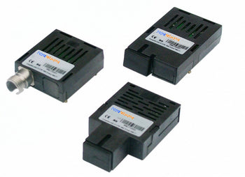
HFBR-1521Z | HFBR-2521Z | AFBR-1629Z | HFBR-2629Z AVAGO compatible full series
-
Совместимый с Cisco 10GBASE-BX20-D BiDi SFP+ 1330 нм-TX/1270 нм-RX 20 км DDM Simplex LC SMF модуль трансивера
Обычная цена $0.00Обычная цена -
AVAGO HFBR-1521Z Совместимое оптоволокно 650 нм Высокопроизводительное оптоэлектронное приемопередающее устройство DC-5 Мбод
Обычная цена $0.00Обычная цена -
AVAGO HFBR-1521Z Совместимое оптоволокно 650 нм Высокопроизводительное оптоэлектронное приемопередающее устройство DC-5 Мбод
Обычная цена $0.00Обычная цена -
AVAGO HFBR-1521Z Совместимое оптоволокно 650 нм Высокопроизводительное оптоэлектронное приемопередающее устройство DC-5 Мбод
Обычная цена $0.00Обычная цена


Power and Wavelength Testing
Test the signal delivering strength and wavelength, to ensure the signal decoding capacity of the receiver, and the wavelength remains consistent from the transmitter to the receiver.

Traffic Testing
Test the bit error rate and packet loss rate, to make them meet the corresponding standards and ensure the performance of transceivers.

Optical Performance Testing
Test the transceivers' eye diagram situation, receiving sensitivity, extinction ratio, wavelength, light-emitting, light-receiving, current and voltage, to ensure the signal quality, stability and reliability of the transmission.

End Face Testing
Check the end face of the transceivers and keep them clean for more stable data transmission, better performance, and durability.

Various Switch Tests
Every module is quality tested for compatibility in the multi-brand switches environment, guaranteeing flawless operations.