


Part Number: MC-FCE-SC-6
FC equip to SC Multimode OM1 62.5/125 Mode Conditioning Patch Cable
F-tone manufactures and supplies standard and custom length 50/125, 62.5/125 and OEM equivalent mode conditioning fiber optic patch cords for 1000BASE-LX/LH Gigabit Ethernet (1300nm long wavelength) applications installed into existing multimode cable plants. These specialized cords help avoid Differential Mode Delay (DMD) effects that can occur when long wave transceiver modules operate at both single-mode and multimode wavelengths. And they are available with FC,ST, SC, LC and MT-RJ connectors.
How the Mode Conditioning Cable Works
The need for this conditioning fiber optic patch cord is due to the single-mode launch nature of the -LX or long-wave (1300nm) transceiver modules used for Gigabit Ethernet. Launching a single-mode laser into the center of a multimode fiber can cause multiple signals to be generated that confuse the receiver at the other end of the fiber. In that case, a mode conditioning patch cord eliminates these multiple signals by allowing the single-mode launch to be offset away from the center of a multimode fiber. This offset point creates a launch that is similar to typical multimode LED launches. (see diagram below)
Notes:
How to Install the Mode Conditioning Cable
If your gigabit LX switch is equipped with SC or LC connectors, please be sure to connect the yellow leg (Singlemode) of the cable to the transmit side, and the orange leg (multimode) to the receive side of the equipment. It is imperative that this configuration be maintained on both ends. The swap of transmit and receive can only be done at the cable plant side. (see diagram below)
- In some cases, customers might experience that a link would be operating properly over FDDI-grade, OM1 or OM2 fiber types without MCP. However please note there is no guarantee link will be operating properly over time, and the recommendation remains to use the MCP.
- There is a risk associated to this type of nonstandard deployment without MCP, especially when the jumper cable is an FDDI-grade or OM1 type. In such case the power coupled directly into a 62.5-micron fiber could be as high as a few dBm and the adjacent receiver will be saturated. This can cause high bit error rate, link flaps, link down status and eventually irreversible damaged to the device.
- Mode conditioning patch cords can only convert single-mode to multimode. If you want to convert multimode to single-mode, then a media converter will be required.
- Another alternative for short reaches within the same location is to use a single-mode patch cable. There will be no saturation over single-mode fiber.
Things to Know When Using Mode Conditioning Cables
- Mode conditioning patch cords are usually used in pairs. Which means that you will need a mode conditioning patch cord at each end to connect the equipment to the cable plant.
- Generally, Mode Conditioning patch cords are required for link distances greater than 984 feet (300 meters).
Features
- Increased transmission bandwidth up to 4 times
- Fits existing cabling scheme
- Easy installation
- Removes effects form DMD
- Permanent, low-profile offset closure
- Enables 1000Base-LX/LH optics to be used with Multi-Mode Fibre
- PC, UPC, APC polish types
- Low insertion loss (<1dB)
- Reduced modal noise
- Vcsel laser source into standard multimode fiber
- OFNR rated jacket complies with strict building codes
- Compliant with IEEE 802.3 applications
Application
- Gigabit Ethernet
- Equipment interconnection
- High speed data transfer
- LAN
- Telecom network
MAKE TO ORDER Customizing your Mode Conditioning Cable (options)
| Cable Jacket | Fiber Type | Connetcors | length |
|---|---|---|---|
|
|
First End
|
|
For assistance customizing your Mode Conditioning Cable, please call us at +1-205-282-9089 or email to [email protected].
| InsertionLoss(dB) | Non-ConditionedChannel(Multimode) | |||
| LC | SC | ST | MTRJ | |
| <0.5(max) | <0.5(max) | <0.5(max) | <0.5(max) | |
| ConditionedChannel(MultimodeDirection) | ||||
| LC | SC | ST | MTRJ | |
| <1.0 | <1.0 | <1.0 | <1.0 | |
| ConditionedChannel(Single-modeDirection) | ||||
| LC | SC | ST | MTRJ | |
| >2.0;<22.0 | >2.0;<22.0 | >2.0;<22.0 | >2.0;<22.0 | |
| FerruleMaterial | Ceramic | Ceramic | Ceramic | Thermoplastic |
| HousingMaterial | Composite | Composite | Metal | Composite |
This product belongs to F-tone Networks' optical components product line. For detailed specifications, please contact our sales team. Thank you!
Important Notice:
Performance figures, data and any illustrative material provided in this data sheet are typical and must be specifically confirmed in writing by F-tone Networks before they become applicable to any particular order or contract. In accordance with the F-tone Networks policy of continuous improvement specifications may change without notice.
The publication of information in this data sheet does not imply freedom from patent or other protective rights of F-tone Networks or others. Further details are available from any F-tone Networks sales representative.
HFBR-1414TZ | HFBR-2412TZ AVAGO compatible full series
-
Совместимость с AVAGO HFBR-1414TZ Оптическое волокно 850 нм Высокопроизводительное оптоэлектронное передающее устройство DC-50 Мбод
Обычная цена $0.00Обычная цена -
Совместимость с AVAGO AFBR-2418TZ Оптическое волокно 850 нм Высокопроизводительное оптоэлектронное приемное устройство DC-50 Мбод
Обычная цена $0.00Обычная цена -
AVAGO HFBR-1412TZ Совместимое оптоволокно 850 нм Высокопроизводительное оптоэлектронное приемопередающее устройство DC-5 Мбод
Обычная цена $0.00Обычная цена -
AVAGO HFBR-2412TZ Совместимое оптоволокно 850 нм Высокопроизводительное оптоэлектронное приемопередающее устройство DC-5 Мбод
Обычная цена $0.00Обычная цена

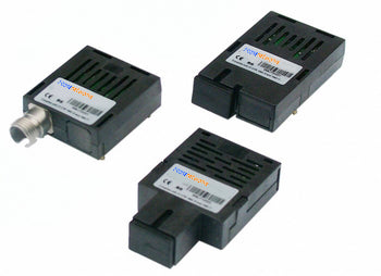
HFBR-1521Z | HFBR-2521Z | AFBR-1629Z | HFBR-2629Z AVAGO compatible full series
-
Совместимый с Cisco 10GBASE-BX20-D BiDi SFP+ 1330 нм-TX/1270 нм-RX 20 км DDM Simplex LC SMF модуль трансивера
Обычная цена $0.00Обычная цена -
AVAGO HFBR-1521Z Совместимое оптоволокно 650 нм Высокопроизводительное оптоэлектронное приемопередающее устройство DC-5 Мбод
Обычная цена $0.00Обычная цена -
AVAGO HFBR-1521Z Совместимое оптоволокно 650 нм Высокопроизводительное оптоэлектронное приемопередающее устройство DC-5 Мбод
Обычная цена $0.00Обычная цена -
AVAGO HFBR-1521Z Совместимое оптоволокно 650 нм Высокопроизводительное оптоэлектронное приемопередающее устройство DC-5 Мбод
Обычная цена $0.00Обычная цена


Power and Wavelength Testing
Test the signal delivering strength and wavelength, to ensure the signal decoding capacity of the receiver, and the wavelength remains consistent from the transmitter to the receiver.

Traffic Testing
Test the bit error rate and packet loss rate, to make them meet the corresponding standards and ensure the performance of transceivers.

Optical Performance Testing
Test the transceivers' eye diagram situation, receiving sensitivity, extinction ratio, wavelength, light-emitting, light-receiving, current and voltage, to ensure the signal quality, stability and reliability of the transmission.

End Face Testing
Check the end face of the transceivers and keep them clean for more stable data transmission, better performance, and durability.

Various Switch Tests
Every module is quality tested for compatibility in the multi-brand switches environment, guaranteeing flawless operations.