


AVAGO AFBR-1629Z Compatible 650nm optical fiber The DC-50 MBd high-performance photoelectric transceiver device
product presentation
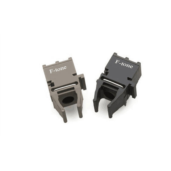
FT-1629Z / 2529Z series fiber optic transceiver devices, which can be used with 650nm plastic fiber, provide high performance and low cost optical fiber communication links for industrial, power generation, medical, transportation and game applications.
FT-1629Z / 2529Z is fully compatible with AVAGO’s AFBR-1629Z / 2529Z series, which supports industry standard plastic fiber interface and provides horizontal structure. FT-1629Z / 2529Z can accommodate plastic fiber with diameter 1mm and PCS fiber with diameter 200 μm, with plastic fiber with 1mm diameter, to achieve a minimum transmission distance of 50 meters.
FT-1629Z is a transmitter, which is composed of a high power LED chip with a peak wavelength of 650nm and its driver chip. The plastic fiber with 1mm core diameter output a typical optical power value of-2 dBm at 5 V power supply voltage. FT-2529Z is a receiver composed of a high-gain span resistance amplifier with integrated photodiode, output stage is rail-to-rail structure, and final output TTL level. To improve the stability of the output pulse width of the receiver, the receiver chip has designed the automatic artery width calibration circuit with the pulse width distortion within ± 4ns.
Product characteristics
- Data transfer rate: DC-50 MBd
- transmission distance: 50 m
- The output waveform pulse width is stable
- Operating temperature range: -40℃ to 85℃
- Compliance the RoHS criteria
- Adapt to a variety of optical fibers
Product application
- Factory automation
- Lan
- Audio and video applications / game applications
- Industrial networks and the fieldbus
System connection index
Transceiver link photoelectric parameters
|
Parameter |
Symbol |
Min |
Typical |
Max |
unit |
Explain |
|
Signal rate |
DR |
DC |
50 |
MBd |
||
|
Transmission distance |
L |
50 |
m |
DR=50 MBd |
Typical application diagram
Figure 1 Typical application circuit diagram of FT-1629Z / 2529Z
Transmitter index
Transmitter pin definition
|
Pin |
Name |
Definition |
|
1 |
VCC |
Chip power supply |
|
2 |
NC |
NO PIN |
|
3 |
GND |
Chip to |
|
4 |
IN |
signal input |

Absolute maximum rating
|
Parameter |
Symbol |
Min |
Max |
unit |
Explain |
|
Storage temperature |
Ts |
- 40 |
+ 85 |
℃ |
|
|
Working temperature |
Ta |
-40 |
+85 |
℃ |
|
|
Working voltage |
VCCT |
- 0.5 |
6 |
V |
|
|
Signal input voltage |
VIN |
- 0.5 |
VCC+0.5 |
V |
|
|
Circulating lead welding temperature |
260/10 |
℃/s |
Photoelectric performance parameters (operating temperature range-40℃ -85℃, power supply voltage range 3.15V <Vcc<3.46V or 4.75V <Vcc<5.25V)
|
Parameter |
Symbol |
Min |
Typical |
Max |
unit |
Explain |
|
1 mm POF fiber output |
PT |
-5 |
-2 |
+2 |
dBm |
T=25℃ |
|
source current |
ICC |
30 |
40 |
m A |
T=25℃ , V CC=5V |
|
|
28 |
40 |
m A |
T=25℃, VCC=3.3V |
|||
|
Peak radiation wavelength |
PK |
630 |
650 |
680 |
nm |
|
|
Enter high voltage |
VIH |
2 |
VCC+0.3 |
V |
||
|
Input low voltage |
VIL |
-0.3 |
0.8 |
V |
||
|
rise time |
Tr |
5 |
ns |
|||
|
drop-out time |
Tf |
5 |
ns |
Receiver metrics
Receiver pin definition
|
Pin |
Name |
Definition |
|
1 |
V out |
TTL outlet end |
|
2 |
GND |
Chip to |
|
3 |
VCC |
Chip power supply |
|
4 |
NC |
NC |

Absolute maximum rating
|
Parameter |
Symbol |
Min |
Max |
unit |
Explain |
|
Storage temperature |
Ts |
-40 |
+85 |
℃ |
|
|
working temperature |
Ta |
-40 |
+85 |
℃ |
|
|
Circulating lead welding temperature |
260/10 |
℃/s |
|||
|
supply voltage |
VCC |
-0.5 |
6 |
V |
Photoelectric performance parameters (operating temperature range-40℃ -85℃, power supply voltage range 3.15V <Vcc<3.46V or 4.75V <Vcc<5.25V)
|
Parameter |
Symbol |
Min |
Typical |
Max |
unit |
Explain |
|
peak wavelength |
λ |
650 |
nm |
|||
|
Input power at an output of 0 |
PRL |
-23 |
+3 |
dBm |
T=25℃ |
|
|
-22 |
+2 |
dBm |
||||
|
Input power at the output of 1 |
PRH |
- 40 |
dBm |
|||
|
Output voltage at the high output level |
VOH |
2.5 |
VCC+0.3 |
V |
PR=0 |
|
|
Output voltage at low output |
VOL |
-0.3 |
0.4 |
V |
PR=PRLmin |
|
|
source current |
ICC |
20 |
30 |
mA |
||
|
Duty cycle distortion |
P WD |
-4 |
+4 |
ns |
||
|
rise time |
Tr |
5 |
ns |
CL=15pF |
||
|
drop-out time |
Tf |
5 |
ns |
CL=15pF |
||
|
Group delay |
TD |
30 |
ns |
|||
|
Power initialization time |
10 |
15 |
ms |
Overall dimensions drawing (FT-1629Z)
Overall dimensions drawing (FT-2529Z)
List of product models
|
Product model |
Descriptiom |
|
FT-1629Z |
Transmitter |
|
FT-2529Z |
Receive devices |
Important Notice
Performance figures, data and any illustrative material provided in this data sheet are typical and must be specifically confirmed in writing by F-tone Networks before they become applicable to any particular order or contract. In accordance with the F-tone Networks policy of continuous improvement specifications may change without notice.
The publication of information in this data sheet does not imply freedom from patent or other protective rights of F-tone Networks or others. Further details are available from any F-tone Networks sales representative.
HFBR-1414TZ | HFBR-2412TZ AVAGO compatible full series

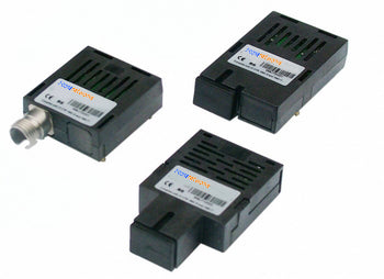
HFBR-1521Z | HFBR-2521Z | AFBR-1629Z | HFBR-2629Z AVAGO compatible full series
-
HFBR-1531Z,HFBR-2531Z,HFBR-1531Z 100% Compatible with Avago ,HFBR-2531Z 100% Compatible with Avago
Regular price $0.00Regular price -
AVAGO HFBR-2521ETZ Compatible Domestic Alternative Optical Module
Regular price $0.00Regular price -
AVAGO HFBR-1521ETZ Compatible Domestic Alternative Optical Module
Regular price $0.00Regular price -
AVAGO HFBR-1528Z Compatible Domestic Alternative Optical Module
Regular price $0.00Regular price


Power and Wavelength Testing
Test the signal delivering strength and wavelength, to ensure the signal decoding capacity of the receiver, and the wavelength remains consistent from the transmitter to the receiver.

Traffic Testing
Test the bit error rate and packet loss rate, to make them meet the corresponding standards and ensure the performance of transceivers.

Optical Performance Testing
Test the transceivers' eye diagram situation, receiving sensitivity, extinction ratio, wavelength, light-emitting, light-receiving, current and voltage, to ensure the signal quality, stability and reliability of the transmission.

End Face Testing
Check the end face of the transceivers and keep them clean for more stable data transmission, better performance, and durability.

Various Switch Tests
Every module is quality tested for compatibility in the multi-brand switches environment, guaranteeing flawless operations.