


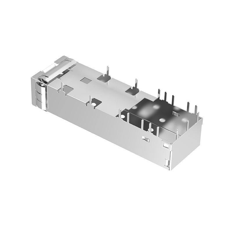
FT11AC02000 1x1 Single-Port SFP Cage Technical Overview
The FT11AC02000 is an industry-standard 1x1 single-port SFP cage assembly featuring solderless press-fit PCB mounting and perimeter metallic EMI spring fingers engineered for 1Gb/s Ethernet, Fast Ethernet, and Fibre Channel networking platforms. Constructed from high-conductivity nickel-plated copper alloy, it provides discrete single-port I/O placement, low transfer impedance chassis EMI grounding, and reliable mechanical transceiver retention for enterprise switches, media converters, and industrial telecom infrastructure.
- Mechanical Form Factor: 1x1 Single-Port SFP Cage Assembly in a lightpipe-free low-profile footprint (1.919" L x 0.551" W x 0.384" H / 48.75mm L x 14.00mm W x 9.75mm H).
- Signal Ecosystem Support: Engineered for Gigabit Ethernet (1GbE), Fast Ethernet, 1G/2G/4G Fibre Channel, and SONET/SDH SFP optical transceivers and copper cable assemblies.
- Board Mount Technology: Solderless Through-Hole Press-Fit termination with nickel-plated copper alloy body for high contact normal force and PCB retention.
- Cross-Reference Sourcing: Direct footprint-compatible drop-in alternative to industry 1x1 SFP press-fit cages from TE Connectivity, Molex, and Amphenol for supply chain diversification.
FT11AC02000 SFP Cage Product Overview
FT11AC02000 is a 1x1 single-port SFP cage assembly featuring external perimeter metallic EMI spring fingers, nickel-plated copper alloy construction, and press-fit PCB mounting. Designed for discrete I/O interface placement on host system boards, this single-port assembly provides low transfer impedance grounding, structural transceiver retention, and thermal stability across an extended operating temperature range (-55°C to +85°C).
Key Benefits of F-tone FT11AC02000 SFP Cage
- High-Reliability Discrete Single-Port Integration: Standalone 1x1 port matrix layout provides hardware PCB designers maximum trace routing versatility and placement flexibility across line card topologies.
- 360-Degree External EMI Spring Finger Containment: Perimeter metallic spring fingers establish resilient, low-impedance grounding contact against chassis bezel cutouts for superior electromagnetic containment.
- Durable Nickel-Plated Copper Alloy Body: Formed from high-conductivity copper alloy with premium nickel plating, offering low transfer contact resistance and high insertion wear resistance over repeated module cycles.
- Solderless Through-Hole Press-Fit Integration: Precision press-fit compliant pins enable automated board insertion without subjecting sensitive motherboard substrates and adjacent SMT components to solder reflow thermal stress.
- Extended Temperature Operating Envelope (-55°C to +85°C): Built for long-term electrical and mechanical reliability in demanding enterprise data centers, outdoor telecom cabinets, and industrial networking hubs.
- Multi-Source Drop-In Compatibility: Standard SFP MSA mechanical footprint enables seamless deployment alongside original OEM equipment for BOM cost optimization and lead-time reduction.
1x1 Single-Port SFP Architecture & PCB Routing Flexibility
Engineered in compliance with SFP MSA (SFF-8472 / INF-8074i) mechanical specifications, the FT11AC02000 features a standalone 1x1 single-port footprint. This discrete architecture allows PCB layout engineers to position individual SFP ports in optimal locations near switching silicon or optical engines, minimizing differential trace lengths and reducing high-speed signal attenuation.
Streamlined Low-Profile Footprint & Press-Fit Board Mounting
The right-angle board mount geometry features an overall height of just 9.75mm [0.384 in] above the PCB, making it ideal for compact 1RU switch faceplates, PCI Express expansion cards, and space-constrained industrial enclosures. Solderless press-fit pins install firmly into plated through-holes (PTH), establishing strong mechanical retention and electrical grounding without requiring secondary wave soldering.
EMI Shielded SFP Cage Design with Copper Alloy Construction
Operating high-speed serial interfaces requires careful electromagnetic compatibility (EMC) design to control radiated emissions and shield internal differential signal traces from ambient electromagnetic interference.
360-Degree Perimeter EMI Spring Fingers
The FT11AC02000 incorporates heavy-duty metallic spring fingers around the entire outer perimeter of the module port opening. When inserted through the chassis bezel, these springs compress against the metallic faceplate cutout, establishing a continuous, low-impedance grounding loop around the transceiver interface.
Corrosion-Resistant Nickel Plated Copper Alloy
Formed from high-conductivity copper alloy with a protective nickel plating, the cage housing delivers high structural rigidity, mechanical wear resistance, and long-term corrosion protection across an operating temperature range of -55°C to +85°C. This supports system-level EMC design requirements for equipment targeting FCC and CE compliance.
Target Applications: Gigabit Ethernet Switches, Industrial Automation, and Telecom
Combining SFP MSA compliance, single-port discrete placement, EMI spring fingers, and press-fit technology, the FT11AC02000 supports various networking and industrial systems:
- Enterprise Gigabit Ethernet Switches & Routers: Ideal for 1GbE Top-of-Rack (ToR) switches, edge routers, and media converters requiring standalone SFP interfaces.
- Storage Area Networks (SAN): Deployed in 1G, 2G, and 4G Fibre Channel host bus adapters (HBAs), storage array controllers, and SAN expansion modules.
- Industrial Automation & Smart Grid: Suitable for extended temperature industrial Ethernet switches, DIN-rail automation hubs, and substation communication nodes.
How to Select and Verify an SFP Cage Assembly Replacement
When evaluating or sourcing discrete 1x1 SFP cage assemblies for new board designs or supply chain diversification, hardware engineers should verify the following core parameters:
- Interface Speed Generation (SFP vs SFP+): Confirm whether the system interface operates at standard SFP rates (up to 4Gbps for 1GbE / Fibre Channel) or requires higher-frequency SFP+ (10G/16G) cages with tighter EMI tolerances.
- Port Matrix Configuration (1x1 Discrete): Confirm that a 1x1 single-port discrete footprint matches your motherboard layout and panel bezel cutout constraints.
- Mechanical Envelope Dimensions: Verify that the 48.75mm length, 14.00mm width, and 9.75mm height envelope fits within your enclosure height and card slot pitch.
- EMI Shielding Mechanism: Ensure the 360-degree perimeter metallic spring fingers align with your front panel bezel cutout to establish a low-impedance grounding seal.
- Mechanical Drawing Verification: Check press-fit pin hole layouts, grounding peg positions, and physical tolerances against official engineering drawings.
Product Specifications
| F-tone Part Number | FT11AC02000 | Part Status | Active |
| Connector Style | Cage | Connector Type | SFP |
| Cage | COPPER ALLOY,Ni PL ATED | PACKAGING | TRAY PACKAGING |
| Port Matrix Configuration | 1x1 Port | Number of Ports | 1 |
| Operating Temperature Range | -55 ~+85°C | Mounting Style | Through Hole, Right Angle |
| Included Lightpipe | No | Termination | Press-Fit |
| Height (Inches/mm) | 9.70/0.382 | Length (Inches/mm) | 53.20/2.094 |
| Width (Inches/mm) | 14.00/0.551 | EMI Containment Feature Type | EMI Springs |
Contact us.
For any inquiries, please feel free to contact us. We reply within 24 hours.
📧 Email: una@f-tone.com
📱 Mobile / WhatsApp / WeChat: +86 177 6116 3895
Important Notice
Performance figures, data and any illustrative material provided in this data sheet are typical and must be specifically confirmed in writing by F-tone Networks before they become applicable to any particular order or contract. In accordance with the F-tone Networks policy of continuous improvement specifications may change without notice.
The publication of information in this data sheet does not imply freedom from patent or other protective rights of F-tone Networks or others. Further details are available from any F-tone Networks sales representative.
HFBR-1414TZ | HFBR-2412TZ AVAGO compatible full series

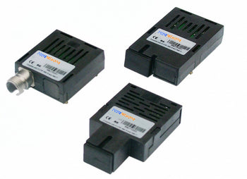
HFBR-1521Z | HFBR-2521Z | AFBR-1629Z | HFBR-2629Z AVAGO compatible full series
-
AVAGO HFBR-2521ETZ Compatible Domestic Alternative Optical Module
Regular price $0.00Regular price -
AVAGO HFBR-1521ETZ Compatible Domestic Alternative Optical Module
Regular price $0.00Regular price -
AVAGO HFBR-1528Z Compatible Domestic Alternative Optical Module
Regular price $0.00Regular price -
AVAGO HFBR-2528Z Compatible Domestic Alternative Optical Module
Regular price $0.00Regular price


Power and Wavelength Testing
Test the signal delivering strength and wavelength, to ensure the signal decoding capacity of the receiver, and the wavelength remains consistent from the transmitter to the receiver.

Traffic Testing
Test the bit error rate and packet loss rate, to make them meet the corresponding standards and ensure the performance of transceivers.

Optical Performance Testing
Test the transceivers' eye diagram situation, receiving sensitivity, extinction ratio, wavelength, light-emitting, light-receiving, current and voltage, to ensure the signal quality, stability and reliability of the transmission.

End Face Testing
Check the end face of the transceivers and keep them clean for more stable data transmission, better performance, and durability.

Various Switch Tests
Every module is quality tested for compatibility in the multi-brand switches environment, guaranteeing flawless operations.