


PZT Fiber Vibrator - Essential Tool for DAS Calibration
- Distributed optical fiber vibration DVS/DAS testing
- PZT-SM Series
| Parameter | FT-161-PZT-SM-2m | FT-161-PZT-SM-Xm |
|---|---|---|
| Max Operating Frequency | 35 kHz | 23 kHz |
| Low-Frequency Operating Frequency | 1 Hz | 1 Hz |
| Fiber Winding Length | 2 m | Customizable 3–10 m |
| External Fiber Length | 0.6 m (IN), 0.6 m (OUT) | 0.6 m (IN), 0.6 m (OUT) |
| Typical Operating Wavelength | 1310/1550 nm | 1310/1550 nm |
| Fiber Type | G652D-SM | G652D-SM |
| Electrical Interface | SMA | SMA |
| Optical Interface | FC/APC | FC/APC |
| Optical Interface Insertion Loss | <0.5 dB | <0.5 dB |
| Dimensions | 70×70×26 mm | 95×94×48 mm |
PZT-Pro Series
| Parameter | FT-161-Pzt-Pro-SM-2m | FT-161-Pzt-Pro-SM-Xm① |
|---|---|---|
| Working Frequency Range② | 0.05 Hz–35 kHz | 0.05 Hz–23 kHz |
| Fiber Winding Length | 2 m | Customizable 3–10 m |
| Pigtail Fiber Length | 0.6 m at both ends | 0.6 m at both ends |
| Fiber Type | G652D-SM | G652D-SM |
| Typical Operating Wavelength | 1310/1550 nm | 1310/1550 nm |
| Optical Interface Type | FC/APC | FC/APC |
| Optical Interface Insertion Loss | <0.5 dB | <0.5 dB |
| Modulation Interface Type | SMA | SMA |
| Modulation Voltage Input Range③ | 10 Vpp (±5V) | 10 Vpp (±5V) |
| Power Supply Interface Type | DC_5.5×2.5 | DC_5.5×2.5 |
| Supply Voltage | DC 5V | DC 5V |
| Supply Current | 1A | 1A |
| Dimensions | L×W×H: 70×70×26 mm | L×W×H: 95×94×48 mm |
| Working Frequency | Modulation Voltage Input | Modulation Waveform |
|---|---|---|
| ≥20 kHz | Vpp ≤ 0.01 V | Sine wave |
| [18, 19] kHz | Vpp ≤ 0.02 V | Sine wave |
| [16, 17] kHz | Vpp ≤ 0.03 V | Sine wave |
| [14, 15] kHz | Vpp ≤ 0.04 V | Sine wave |
| [12, 13] kHz | Vpp ≤ 0.05 V | Sine wave |
| [10, 11] kHz | Vpp ≤ 0.06 V | Sine wave |
| [8, 9] kHz | Vpp ≤ 0.07 V | Sine wave |
| [6, 7] kHz | Vpp ≤ 0.08 V | Sine wave |
| [4, 5] kHz | Vpp ≤ 0.09 V | Sine wave |
| [2, 3] kHz | Vpp ≤ 0.1 V | Sine wave |
| [0.9, 1] kHz | Vpp ≤ 0.2 V | Sine wave |
| [0.7, 0.8] kHz | Vpp ≤ 0.3 V | Sine wave |
| [0.5, 0.6] kHz | Vpp ≤ 0.4 V | Sine wave |
| [0.3, 0.4] kHz | Vpp ≤ 0.5 V | Sine wave |
| [0.1, 0.2] kHz | Vpp ≤ 0.6 V | Sine wave |
| (5, 10) Hz | Vpp ≤ 1 V | Sine wave |
| [1, 5) Hz | Vpp ≤ 3 V | Sine wave |
| [0.5, 1) Hz | Vpp ≤ 5 V | Sine wave |
| [0.1, 0.5) Hz | Vpp ≤ 7 V | Sine wave |
| [0.05, 0.1) Hz | Vpp ≤ 9 V | Sine wave |
Notes
- Modulation voltage input must not exceed 10 Vpp (±5 V). Damage caused by over-limit input is not covered by warranty.
- The Vpp values in the table are recommended values. Due to individual differences in piezoelectric ceramic tubes, if the waveform is unstable, fine-tune Vpp for optimal performance.
- For parameters not listed, follow the rule "the higher the working frequency, the lower the modulation voltage input Vpp", keeping the working frequency and input voltage within the specified ranges.
Professor Wu from F-tone Networks was selected as one of the top 2% global scientists for four consecutive years from 2022 to 2025 (https://elsevier.digitalcommonsdata.com/datasets/btchxktzyw/6)
F-tone Networks Technical Support:
Email:una@f-tone.com
WhatsApp and WeChat: +86177 6116 3895
Important Notice
Performance figures, data and any illustrative material provided in this data sheet are typical and must be specifically confirmed in writing by F-tone Networks before they become applicable to any particular order or contract. In accordance with the F-tone Networks policy of continuous improvement specifications may change without notice.
The publication of information in this data sheet does not imply freedom from patent or other protective rights of F-tone Networks or others. Further details are available from any F-tone Networks sales representative.
HFBR-1414TZ | HFBR-2412TZ AVAGO compatible full series

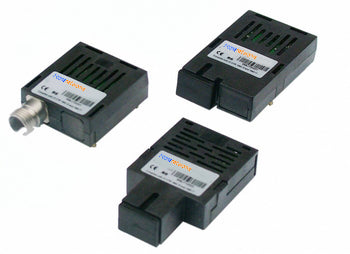
HFBR-1521Z | HFBR-2521Z | AFBR-1629Z | HFBR-2629Z AVAGO compatible full series
-
HFBR-1531Z,HFBR-2531Z,HFBR-1531Z 100% Compatible with Avago ,HFBR-2531Z 100% Compatible with Avago
Regular price $0.00Regular price -
AVAGO HFBR-2521ETZ Compatible Domestic Alternative Optical Module
Regular price $0.00Regular price -
AVAGO HFBR-1521ETZ Compatible Domestic Alternative Optical Module
Regular price $0.00Regular price -
AVAGO HFBR-1528Z Compatible Domestic Alternative Optical Module
Regular price $0.00Regular price


Power and Wavelength Testing
Test the signal delivering strength and wavelength, to ensure the signal decoding capacity of the receiver, and the wavelength remains consistent from the transmitter to the receiver.

Traffic Testing
Test the bit error rate and packet loss rate, to make them meet the corresponding standards and ensure the performance of transceivers.

Optical Performance Testing
Test the transceivers' eye diagram situation, receiving sensitivity, extinction ratio, wavelength, light-emitting, light-receiving, current and voltage, to ensure the signal quality, stability and reliability of the transmission.

End Face Testing
Check the end face of the transceivers and keep them clean for more stable data transmission, better performance, and durability.

Various Switch Tests
Every module is quality tested for compatibility in the multi-brand switches environment, guaranteeing flawless operations.